Step 1. Preparing the Fibers
1. Strip jacket and remove an adequate amount of jacket, usually 2-3 m, for splicing and dressing the buffer tubes and fibers in the splice closure. Leave the proper amount of strength members to attach the cable to the closure. Refer to the splice closure directions for lengths needed. Clean all water-blocking materials using appropriate cleaners.
2. Remove buffer tubes exposing fibers for splicing. Generally, splice closures will require ~1 m buffer tubes inside the closure to and ~ 1 m fiber inside the splice tray. Clean all water-blocking materials.
3. Each fiber must be cleaned thoroughly before stripping for splicing.
4. When ready to splice a fiber, strip off the buffer coating(s) to expose the proper length of bare fiber.
5. Clean the fiber with appropriate wipes.
6. Cleave the fiber with an appropriate fiber cleaver.
7. Place the fiber into the fusion splicing machine and clamp it in place.
Step 2. Running the splicer program
1. Choose the proper program for the fiber being spliced.
2. The splicer will show the fibers being spliced on the video screen.
3. Fiber ends will be inspected for proper cleaves and bad ones like the one on the right above will be rejected.
4. Automated Splicing
5. Fibers will be moved into position.
6. Prefuse cycle will remove any dirt on the fiber ends and preheat the fibers for splicing.
7. The fibers will be aligned using core alignment method for that splicer.
8. The fibers will be fused by an automatic arc cycle that heats them in an electric arc and feeds the fibers together at a controlled rate.
9. When fusion is completed, the splicing machine will inspect the splice and estimate the optical loss of the splice. It will tell the operator if a splice needs to be remade.
10. The operator will remove the fibers from the guides and attach a permanent splice protector by heat-shrinking or clamping clam shell protectors.
Step 3. Evaluating Splices
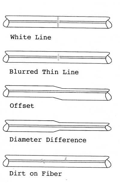
Good Splices: Visually inspect splice after the program has run, using both X and Y views. Some flaws that do not affect optical transmission are acceptable, as shown. Some fibers (e.g. fluorine-doped or titanium coated) may cause white or black lines in splice region that are not faults.
Bad Splices: Some flaws are unacceptable and require starting the splicing process over. Some, like black spots or lines, can be improved by repeating the ARC step, but never more than twice. For large core offsets, bubbles or bulging splices, always redo.

Step 4. Protecting the fiber
Protecting the fiber from bending and tensile forces will ensure the splice not break during normal handling. A typical fusion splicing has tensile strength between 0.5 and 0.5 pounds, and won't break during normal processing. But it still needs to be protected from excessive bending and drag force. Use heat shrinkable tube, silica gel, and/or mechanical crimping protector will remain joint protection from external elements and breakage.
In general, fusion splicing takes a longer time to complete than mechanical splicing. Also, yields are typically lower making the total time per successful splice much longer for fusion splicing. Both the yield and splice time are determined to a large degree by the expertise of the fusion splice operator. Fusion splice operators must be highly trained to consistently make low-loss reliable fusion splices. For these reasons the fusion splice is not recommended for use in Navy shipboard applications.


 IPv6 network supported
 English
 русский
 español
 português

 sales@seikofire.com
